Building a basic RFID card reader
Background
Access cards are used everywhere on a day to day business, ranging from highly secure facilities to medium scale enterprises to small businesses. Most access cards use some kind of Radio Frequency ID (RFID) technology.
In this project, I used an Arduino to construct an RFID reader, to read data off the card and identify what type of card is being presented. I’d like to further develop this to include card cloning, and then possibly recreate the entire setup on a single PCB board and have a cheaper in-house on the go version of the proxmark3 tool.
For the time being this blog will provide a step-by-step guide on how to recreate the setup, and explain the code which allows us to read the cards. But first, a demo…
Demo Video
Requirements
Software: Arduino IDE or VSCode (with Arduino plugin).
Hardware: Arduino Uno, Adafruit PN532 Shield, Adafruit RGB LCD Screen, SD Card Reader (Optional)
Code: Modified Adafruit PN532 Library (Link provided)
Hardware Setup
Some other requirements are basic soldering ability and equipment. With everything at hand, we can start to piece together the setup and create our RFID card reader.
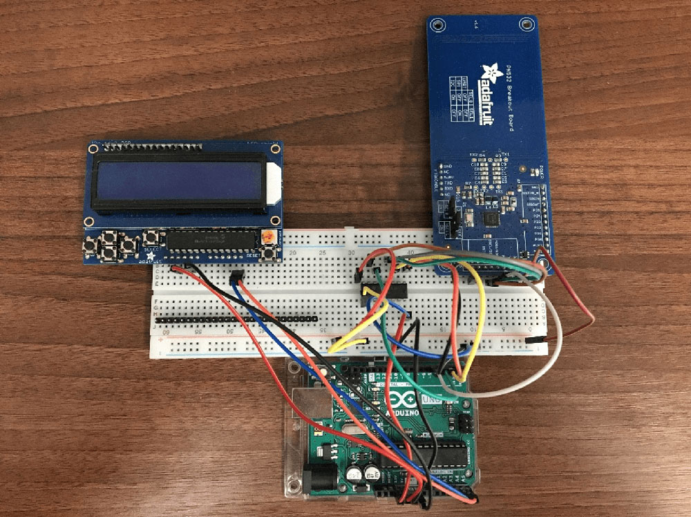
As we can see we have three main parts to our setup; the Arduino which obviously is the core of the project, the LCD Screen used to display menu options, and the RFID shield which will be the focus of this project.
ADAFRUIT PN532 BREAKOUT BOARD
The PN532 Breakout Board comes with its own library which I slightly modified in order to boost its capabilities. Below we can see the actual board with the soldered pins.
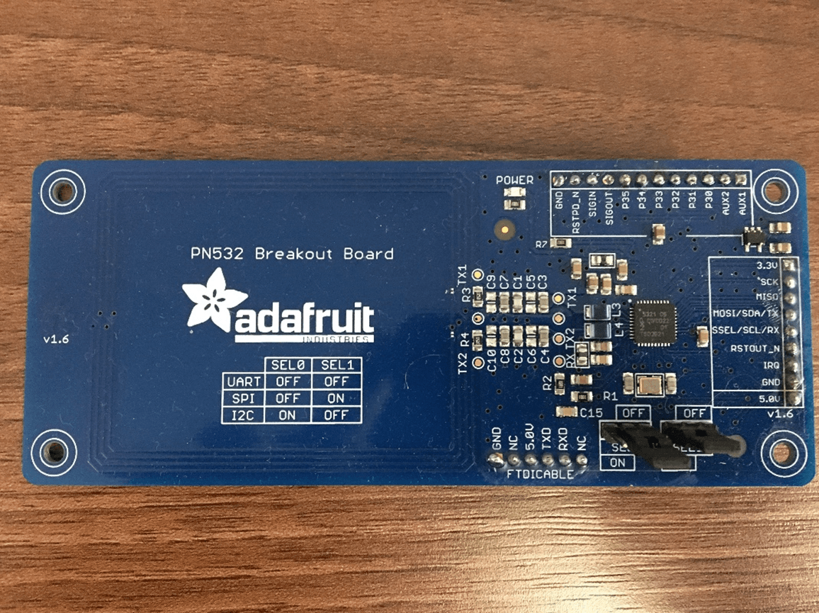
Figure 3.2: The PN532 Breakout Board with Soldered Pins
Directly under the large adafruit logo, we can see variations of the selection pins SEL0 and SEL1, which allow us to configure which bus over which we’d like to communicate. For this project we’ll be using the SPI bus.
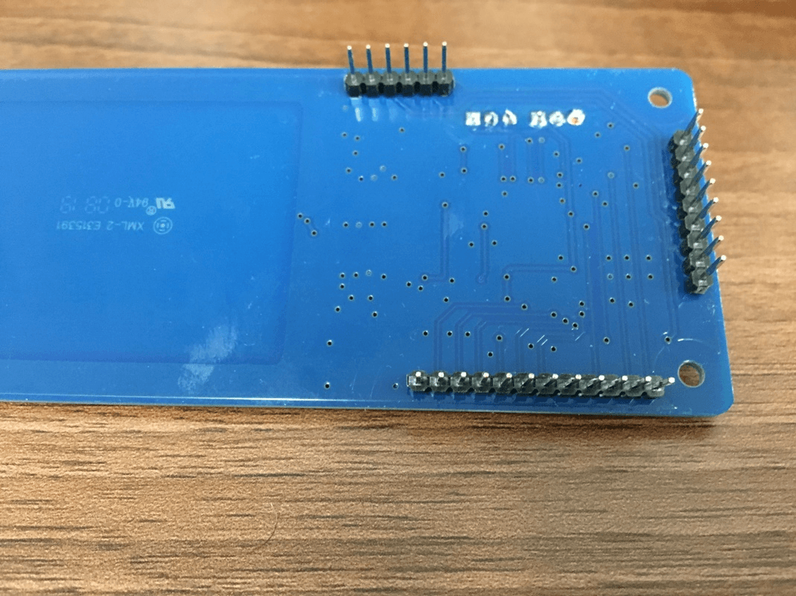
Figure 3.3: The underside of the PN532 Breakout Board
On the bottom of the board we can see the long side of the headers which we’ve soldered on. These will slot into our breadboard; it will also allow the marked side to stay visible allowing us to configure the wires easily.
For further instructions on how to build and configure a naked PN532 Breakout Board, you can checkout Adafruit’s Guide. I followed their guide and it was pretty straight forward and easy to setup.
Adafruit RGB LCD Shield Kit
The RGB LCD Shield kit comes equipped with everything you would need for a menu screen selector. It comes with buttons, which can be configured or simply left unused. Its support library is pretty complete, although the buttons do not have any de-bouncing methods, but we manage to overcome this, as shown later.
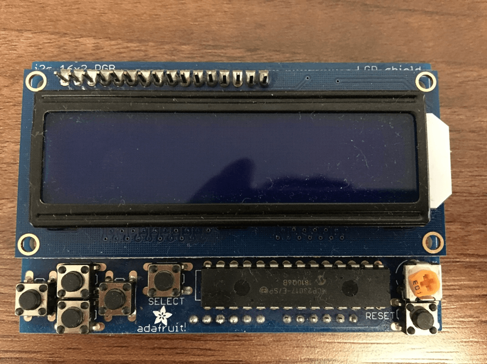
Figure 3.4: RGB LCD Shield with Buttons and Chip Soldered On
This is what the final product of the screen will look from the front. As you can see the actual LCD Screen is layered on the shield, and the buttons are connected to that shield. The buttons are configurable and together it makes for a nice user interface.
Once again, for a more comprehensive guide or any unanswered questions, I highly recommend visiting Adafruit’s Guide on setting up the screen. Especially if you wish to experiment anything outside the scope of this project and use the screen for other projects.
Source Code
Getting the chance to solder and mess around with hardware is always fun, but the real work comes in the software implementation. Unfortunately, the PN532 Breakout Board’s library did not accommodate for our needs so we had to slightly alter it to get the information we needed.
In order to make my code (somewhat) clean I separated the RFID functionality, the LCD screen functionality and of course the Arduino’s main class, which utilises the former two. Since variables and libraries are all shared amongst each other with Arduino files, I’ve decided to store all of them in the RFID_Main.ino file.
#include <Wire.h>
#include <SPI.h>
#include <Adafruit_PN532.h>
#include <Adafruit_RGBLCDShield.h>
#include <utility/Adafruit_MCP23017.h>

// If using the breakout with SPI, define the pins for SPI communication.
#define PN532_SCK  (2)
#define PN532_MOSI (3)
#define PN532_SS   (4)
#define PN532_MISO (5)

// If using the breakout or shield with I2C, define just the pins connected
// to the IRQ and reset lines.  Use the values below (2, 3) for the shield!

#define PN532_IRQ   (2)
#define PN532_RESET (3)  // Not connected by default on the NFC Shield

// Use this line for a breakout with a software SPI connection (recommended):
Adafruit_PN532 nfc(PN532_SCK, PN532_MISO, PN532_MOSI, PN532_SS);
Adafruit_RGBLCDShield lcd = Adafruit_RGBLCDShield();

#if defined(ARDUINO_ARCH_SAMD)
// for Zero, output on USB Serial console, remove line below if using programming port to program the Zero!
// also change #define in Adafruit_PN532.cpp library file
#define Serial SerialUSB
#endif
This may be important to know beforehand, since I will explain the RFID_Main.ino file last, but will often reference variables or libraries initialised here. However, before we dig into any of the code, let’s have a look at the modified library.
Modified Library
Big thanks to Adafruit for having an open source library with examples, as well as making their hardware compatible with the NFClib library. We won’t be looking at the NFClib library in this project, but it is widely used among very popular devices such as the proxmark3, and could be used for cloning cards with this setup (I have yet to explore if it’s possible using the PN532 library but I will be sure to update this once I have).
In order to successfully determine the card type we are dealing with, we must find the SAK Value. The SAK Value is a hex value which determines the type of card we are dealing with.
/**************************************************************************/
/*!
    Sets the MxRtyPassiveActivation byte of the RFConfiguration register

    @param  sakValue    Holds the value of the SAK attribute

    @returns 1 if everything executed properly, 0 for an error
*/
/**************************************************************************/
bool Adafruit_PN532::readCardSAK(uint8_t cardbaudrate, uint8_t * sakValue, uint16_t timeout) {
  pn532_packetbuffer[0] = PN532_COMMAND_INLISTPASSIVETARGET;
  pn532_packetbuffer[1] = 1;  // max 1 cards at once (we can set this to 2 later)
  pn532_packetbuffer[2] = cardbaudrate;

  if (!sendCommandCheckAck(pn532_packetbuffer, 3, timeout))
  {
    #ifdef PN532DEBUG
      PN532DEBUGPRINT.println(F("No card(s) read"));
    #endif
    return 0x0;  // no cards read
  }

  // wait for a card to enter the field (only possible with I2C)
  if (!_usingSPI) {
    #ifdef PN532DEBUG
      PN532DEBUGPRINT.println(F("Waiting for IRQ (indicates card presence)"));
    #endif
    if (!waitready(timeout)) {
      #ifdef PN532DEBUG
        PN532DEBUGPRINT.println(F("IRQ Timeout"));
      #endif
      return 0x0;
    }
  }

  // read data packet
  readdata(pn532_packetbuffer, 20);

  /* ISO14443A card response should be in the following format:

    byte            Description
    -------------   ------------------------------------------
    b0..6           Frame header and preamble
    b7              Tags Found
    b8              Tag Number (only one used in this example)
    b9..10          SENS_RES
    b11             SEL_RES
    b12             NFCID Length
    b13..NFCIDLen   NFCID                   */

  if (pn532_packetbuffer[7] != 1)
    return 0;

  *sakValue = pn532_packetbuffer[11];
  return 1;
}
Using bits from Adafruits pre-existing functions I was able to create a new method which spits out the SAK Value of the card. At first, I tried to access the readdata function by making it public, however this proved troublesome as I would need to modify the header files and make various changes. Instead I opted to create a function which takes in a uint8_t variable, uses the readdata method which pulls the information from the card being read by the PN532, and then stores the SAK value in the variable passed.
The readdata method can be found within the library, so if you want you can have a look through their GitHub Repo and check it out. Now, you may be wondering how I knew at what index in pn532_packetbuffer was the SAK value stored. Well while going through Adafruit’s library I came across the readPassiveTargetID method, which contained some debug information. You guessed it; they print out the SAK value along with its value taken from the pn532_packetbuffer variable.
#ifdef MIFAREDEBUG
    PN532DEBUGPRINT.print(F("ATQA: 0x"));  PN532DEBUGPRINT.println(sens_res, HEX);
    PN532DEBUGPRINT.print(F("SAK: 0x"));  PN532DEBUGPRINT.println(pn532_packetbuffer[11]);
#endif
LCD Screen Functions
I found it tedious to continuously have to call certain functions to format printing on the screen. It was adding too much to my code and making it look ugly. Instead I decided to make a separate file where I created functions to format the printing methods, making it easier to read the code.
#define WHITE 0x7

int selector = 0;
String toDisplay[3] = {"1.Get UID", "2.Card Info", "3.Clone Card"};

void startScreen() {
  lcd.begin(16, 2);
  lcd.setBacklight(WHITE);
}
This what the start of the file looks like; we define the background colour using a hex value (pulled from Adafruits docs). We then initialise a selector variable and a toDisplay array. The selector variable will be used to select items from the menu options provided by toDisplay. As I’m writing this, the “Clone Card” option isn’t available, but hopefully it will be soon!
The startScreen method turns on the actual screen for it to be used. We then set the backlight and we’re now ready to use the screen.
void start() {
  // Got ok data, print it out!
  lcd.clear();
  lcd.setCursor(0, 0);

  lcd.print(toDisplay[0]); lcd.setCursor(15, 0); lcd.print("<");
  lcd.setCursor(0, 1);
  lcd.print(toDisplay[1]);
}
The start method boots up the menu screen. It clears anything that’s already on the screen, sets the cursor to the initial position, then prints the first two menu options (since the screen can only fit two lines) and puts the “<“ as a selector marker.
void printFirstLine(String s1) {
  lcd.setCursor(0,0);
  lcd.print(s1);
}

void printSecondLine(String s1) {
  lcd.setCursor(0,1);
  lcd.print(s1);
}

void printDataDEC(uint32_t data) {
  lcd.print(data, DEC);
}

void printDataHEX(uint32_t data) {
  lcd.print(data, HEX);
}

void printUID(uint8_t num) {
  lcd.print(num, HEX);
}

void reset() {
  lcd.clear();
  lcd.setCursor(0,0);
}

void printLines(String s1, String s2) {
    lcd.clear();
    lcd.setCursor(0, 0);
    lcd.print(s1);
    lcd.setCursor(0,1);
    lcd.print(s2);
}
The above functions are all various formats for printing or clearing the screen, I found it easier than having to rewrite the functions every time. They’re pretty self-explanatory. printDataHEX and printDataDEX are used to print informational data of size 32 bytes. printUID simply takes a unit8_t number and prints it as a hex value on the screen, this is needed otherwise it won’t be parsed properly. Lastly printLines takes in two strings, and prints each string on a separate line, I found this one to be the most helpful rather than having to retype the contents of that function every single time.
unsigned long lastDebounceTime = 0;
unsigned long debounceDelay = 50;
void menu() {
  uint8_t buttons = lcd.readButtons();

  if (buttons) {
    reset();

    if (buttons & BUTTON_UP) {
      if ((millis() - lastDebounceTime) > debounceDelay) {
        switch(selector) {

          case 0:
            printLines(toDisplay[selector], toDisplay[selector+1]);
            lcd.setCursor(15, selector);
            lcd.print("<");
            break;

          case 1:
            selector--;
            printLines(toDisplay[selector], toDisplay[selector+1]);
            lcd.setCursor(15, selector);
            lcd.print("<");
            break;

           case 2:
            selector--;
            printLines(toDisplay[selector], toDisplay[selector+1]);
            lcd.setCursor(15, selector-1);
            lcd.print("<"); break; } } } if (buttons & BUTTON_DOWN) { if ((millis() - lastDebounceTime) > debounceDelay) {
        switch(selector) {

          case 0:
            selector++;
            printLines(toDisplay[selector-1], toDisplay[selector]);
            lcd.setCursor(15, selector);
            lcd.print("<");
            break;

          case 1:
            selector++;
            printLines(toDisplay[selector-1], toDisplay[selector]);
            lcd.setCursor(15, selector-1);
            lcd.print("<");
            break;

          case 2:
            printLines(toDisplay[selector-1], toDisplay[selector]);
            lcd.setCursor(15, selector-1);
            lcd.print("<");
            break;
        }
      }
    }

    if (buttons & BUTTON_SELECT) {
      if (selector == 0) {
        getMifareUID();
      } else if (selector == 1) {
        readCard();
      } else {
        clone();
      }
    }

    lastDebounceTime = millis();
  }
}
Lastly, we have the menu function, which displays the menu options and the selector. Due to the buttons not coming with pre-built de-bouncing functions I had to implement it myself. This was the first time I worked with de-bouncing, and I found it somewhat cumbersome, but a learning experience, nonetheless. If you haven’t heard of or worked with de-bouncing previously, I’ve written a small paragraph about it detailing my code at the end of this section.
Apart from the de-bouncing code, the rest is pretty comprehensive, but I’ll go through it to explain my logic behind it. I had the selector value and the array of options to be displayed on the screen. Since the screen only had two lines, I needed it to work such that if the selector “<“ character was pointed at the second option, but still displaying the first two options, and the user clicked the down button, then it would update the screen so that the first line was now the second option, the second line was now the third option and the selector was pointing at the third option. This had to work vice versa, so when moving upward the same logic had to apply.
Assuming that we’ve configured the de-bouncing correctly, each press should correspond to a single click, allowing us to incrementally change our selector variable. In the case that our selector value is at 0, meaning it is displaying the first two options, and the button being pressed is DOWN, then we increment the selector. Once this is done, we will print to the screen the values of the array at index, selector-1, and selector, respectively. We do this for every case, however once we reach case 2, we do not increment the selector since that would produce an array out of bounds exception, instead we simply shift, the “<“ down.
For moving upwards, we apply the same logic, instead using the inverse. So, we would decrement the selector, and if we’re at the top option we won’t decrement it, and displaying the items works the same way.
The selecting option was easy in this case, I simply hard-coded the calls to the respective menu options, and that was that. Now assuming de-bouncing is working and the selector is representing the correct option (which it should be doing if the de-bouncing is working), then we can just use the selector to determine which call to make.
De-Bouncing
If you’re like me and haven’t heard of de-bouncing before, it occurs when you press a button one time, but it registers multiple presses (electricity works fast). The process of making it so that only one press is registered is known as de-bouncing.
The way I got around this was by, recording the current time as it’s being pressed, subtracting it from the lastDebounceTime and comparing it to the debounceDelay. The lastDebounceTime variable is updated every time we finish pressing a button and is set to the current time. If the value was not updated then we would never be able to tell the timing between presses, so it is important that we update the value. debounceDelay is a custom value I got by fiddling around with the buttons and testing it out. Basically, whatever feels most natural to your pressing should be the value of debounceDelay.
RFID Funtions
The PN532 is primarily utilised through the CardFunctions.ino file, which contains all the methods I’ve implemented for this project.
void startReader() {
  nfc.begin();
}

void getBoardFirmware(uint32_t versiondata) {
  versiondata = nfc.getFirmwareVersion();
}

void configToRead() {
  // configure board to read RFID tags
  nfc.SAMConfig();
}
These are some starter functions to just prepare the PN532 board on start up. As you can see, we can start the reader, we can get the board firmware and we can configure the board to start reading when we’re ready.
//Returns the UID of the card being read
void getMifareUID() {
  uint8_t success;
  uint8_t uid[] = { 0, 0, 0, 0, 0, 0, 0 };  // Buffer to store the returned UID
  uint8_t uidLength;                        // Length of the UID (4 or 7 bytes depending on ISO14443A card type)


  // Wait for an ISO14443A type cards (Mifare, etc.).  When one is found
  // 'uid' will be populated with the UID, and uidLength will indicate
  // if the uid is 4 bytes (Mifare Classic) or 7 bytes (Mifare Ultralight)
  printLines("Waiting for an", "ISO14443A Card...");
  success = nfc.readPassiveTargetID(PN532_MIFARE_ISO14443A, uid, &uidLength);

  if (success) {
    // Display some basic information about the card
    printLines("Found ISO14443A card", "UID: ");
    for (int i = 0; i < uidLength; i++) {
      printUID(uid[i]);
    }
  }
}
Assuming you’re ready to start reading, we can call getMifareUID which will use Adafruit’s pre-built method to read the UID. It simply gets a response packet from the hardware, parses it, and then updates uid and uidLength variable passed to it. It will then print to the LCD Screen using the function created in the LCDScreen.ino file, printLines and printUID, explained in the previous section.
// Finds the SAK value of the card and then determines what type
// of RFID the card is
void readCard() {
  uint8_t sakValue;
  uint8_t success;

  printLines("Waiting for an", "ISO14443A Card...");
  success = nfc.readCardSAK(PN532_MIFARE_ISO14443A, &sakValue);

  if (success) {
    reset();

    switch (sakValue) {
      case 0:
        printLines("Mifare Ultralight", "Detected");
        break;
      case 8:
        printLines("Mifare Classic", "1K Detected");
        break;
      case 18:
        printLines("Mifare Classic", "4K Detected");
        break;
      case 24:
        printLines("Mifare DESFire", "Detected");
        break;
      default:
        printLines("Could not read", "card");
        break;
    }
  }
}
The read card method, although simple looking, took some time to create. This was mostly due to getting the SAK value from the card. As I mentioned previously, we had to modify the library in order to obtain the information. MIFARE produce several different cards, and in order for certain doors to detect the type of card, it requires a certain value. This value is contained in the manufacture block and it’s a hex value which distinguishes each card type. I used the MIFARE docs, found here, and referred to page 11 which listed the cards with their respective HEX value.
Using this information, it was pretty simple to map the SAK values to their cards. I focused on the most common cards, solely because I wanted to, however you can make this list as thorough as you’d like.
RFID Main
Moving onto the main event, the RFID_Main.ino file, which brings all the functions we saw together to create what we see in the demo below.
void setup() {
  Serial.begin(115200);
  startReader();
  startScreen();

  uint32_t versiondata = nfc.getFirmwareVersion();

  if (! versiondata) {
    reset();
    printFirstLine("Couldn't find");
    printSecondLine("board");
    while (1); // halt
  }

  printFirstLine("Found chip PN5");
  printDataHEX((versiondata >> 24) & 0xFF);
  printSecondLine("Firmware ver. ");
  printDataDEC((versiondata >> 16) & 0xFF);
  delay(1500);
  start();

  configToRead();
}
The setup method begins the PC serial connection, in case you want to implement debugging features, then starts the PN532 for reading and turns on the LCD Screen. We then get the firmware version of the PN532 board to make sure that it’s connected and detected. We then print out some information about the board and the firmware version. We leave it on the screen for a bit, and then we call the start method, which if you recall prints the initial menu options. Then we setup the PN532 board to start reading, and you’re now ready to scan your cards.
void loop() {
  menu();
}
The loop function is simple, since the bulk of the workings happens in the menu method. The menu method is in constant need of refreshing since it needs to constantly check if the buttons are being pressed.
Conclusion and Improvements
This project was interesting, and it included a lot of firsts for me. I soldered for the first time, which was something I’ve been wanting to do for a while. Being a university student, it can be hard to get the budget for these sorts of things but working at the Cyber Lab gave me the opportunity to explore this.
Moreover, I dealt with de-bouncing, which as a fan of low-level programming, was very interesting since I was basically capping the number of times it should register the electrical switch (at the push of a button) to count as an actual press. Of course, when you have your first times, it calls for improvements and these are some which I’m looking to integrate in future projects, as well as the expansion of this project.
Soldering is a skill which comes with practice, and having done it for the first time, I now feel more confident approaching it, however I still need to be more patient when applying the solder and waiting the right amount of time for it to settle. I tend to rush a bit with that.
I feel like the de-bouncing can be smoothed out a little more, but it’s rather mundane having to go load your code each time to check if the button presses had come out right. I settled for what I felt was a good enough de-bouncing time.
Lastly, I’d like to extend this project in the near future to hopefully include card cloning, and possibly card emulation. If done so, we can reproduce the setup on a PCB board much smaller and load up the code onto it recreating a cheaper alternative to the proxmark3. This can be used for red team campaigns and is cost effective.
Fritzing Circuit Diagrams
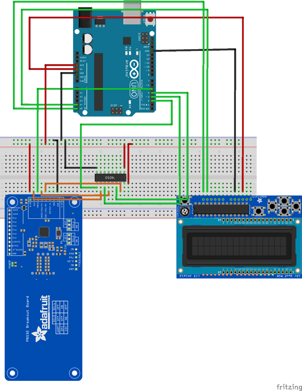
Figure 6.1.1: Breadboard image produced in Fritzing
The red cables represent power connections, the black cables represent ground connections, the green cables represent data connections to the Arduino and lastly the orange cables represent data cables from the PN532 to the level shifter. Fritzing is simple to use with drag and drop components, you simply download a library for the parts you are using, and it will add them to the list of drag and drop items you can use. By producing the above image, it automatically generated the schematic diagram below.
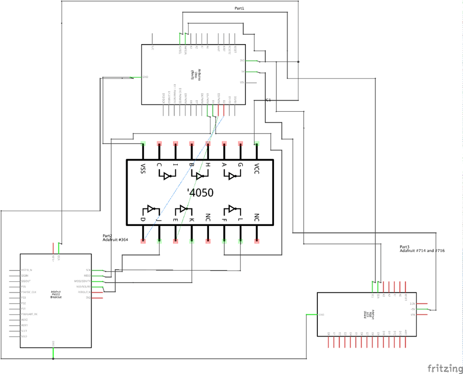
Fritzing is helpful for creating these technical diagrams in a fairly neat way. Some people are more comfortable viewing the schematic rather than the breadboard view, so it’s helpful for reaching a wider audience and saving time in doing so. The fritzing project can be found in the GitHub repo along with the rest of the code.
Helpful Links
- This Project’s GitHub Repo with Libraries: https://github.com/6point6/arduino_RFID_demo
- Mifare Research: Mifare Classic 1K Research
- Mifare SAK Values: https://www.nxp.com/docs/en/application-note/AN10833.pdf
- Adafruit PN532 Product Page: https://www.adafruit.com/product/364
- Adafruit PN532 Guide: https://cdn-learn.adafruit.com/downloads/pdf/adafruit-pn532-rfid-nfc.pdf?timestamp=1574252733
- Adafruit PN532 GitHub Repo: https://github.com/adafruit/Adafruit-PN532
- Using PN532 with NFClib: https://learn.adafruit.com/adafruit-pn532-rfid-nfc/libnfc
- Adafruit RGB LCD Screen Product Page: https://www.adafruit.com/product/714
- Adafruit RGB LCD Screen Guide: https://cdn-learn.adafruit.com/downloads/pdf/rgb-lcd-shield.pdf?timestamp=1574252553
- Adafruit RGB LCD Screen GitHub Repo: https://github.com/adafruit/Adafruit-RGB-LCD-Shield-Library
For our latest research, and for links and comments on other research, follow our Lab on Twitter.